Let’s dive into the last part of this project – picking the right hardware (MCU and supporting components) and develop the software that will make this whole contraption run. If watching the finalized product in action is more your speed, scroll to the end for the YouTube video.
Understanding the Components
The basic components involved in this project are:
-W216 OEM COMAND Controller
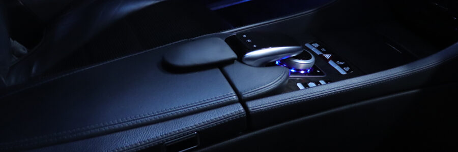
-W222 COMAND Controller
-Navdy Heads Up Display
-Android Headunit
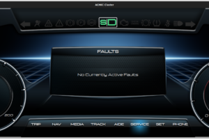
The easiest approach would be to keep the original COMAND controller and have it talk to our MCU, instead of the actual car. In addition to the rotary knob, the original controller handles a variety of other buttons that we would need to replicate if we deleted the controller altogether. It’s much easier to remove all necessary large components from the assembly (knob, motor, etc.) and just keep the main board and let it handle all buttons. This would also allow the car to perform diagnostics and software updates without issues, as the controller is an integral part of the system. If it were missing, software updates would fail and error codes would probably show up during the diagnostics process.
The W222 controller would also talk to our MCU separately. Our MCU would then provide a translation of knob related controls and communicate them to the vehicle. Of course, the MCU would also need to forward all messages coming from the vehicle to the appropriate controller. In addition, our MCU would also need to connect to the Android head unit via USB and act as a standard HID mouse/keyboard and provide mouse functionality from the W222 touchpad.
So, right off the bat, we will need an MCU that can handle at least 3 simultaneous CAN connections. One of the connections would be for the car, the second for the new W222 controller and the last for the original controller. There aren’t many MCUs that can handle this type of communication, along with all the other features we need.
Additionally, we would also need a BLE component that would be able to communicate with out HUD and masquerade as the controller that the Navdy unit shipped with.
Handling the HUD
The Navdy HUD shipped with a remote controller/dial that connects to the unit wirelessly. Upon probing the hardware and connection, it’s clear that it uses BLE to connect to the main HUD unit. Can we replicate this unit within our MCU and have the HUD think it’s talking to its original dial? Thankfully, BLE is very well documented and provided with the right components we should be able to replicate the communication without too much trouble.
So, how does the HUD dial actually work? Long story short, it connects via BLE and transmits standard HID commands to the HUD. Now, clearly we would need to figure out the pairing and all the services/characteristics that the HUD uses, as well as the actual commands being sent.
If you decide to tackle this project on your own, you will need a BLE module that can act as a HID device over BLE and talk to the MCU simultaneously. There are many options so, shop around. The intricacies of BLE communication, and it can get tricky, believe me, are beyond the scope of this article.
MCU CAN Bus Communication
While many MCUs can handle 1 or 2 CAN bus connections, not many can handle 3 at the same time. In addition to the shear number of CAN bus connections needed, our MCU would also need to be speedy to handle all the various calculations and translations, AND the BLE connection. We decided to use the Teensy 4.1. You can never go wrong with a Teensy. The latest version, 4.1, can actually handle multiple threads, 3 CAN bus ports, a myriad of other I/O ports, all at blazing fast speeds.
In addition to the MCU we will need CAN bus transceivers for the actual line communication. We have previously used TJA1050 based modules without issues, so we are sticking with them for this project as well.
Decoding CAN Bus Communication
Most modern vehicles have multiple CAN buses and the first step is to figure out their specs. What speeds to they operate at and what components communicate on these buses? If you have access to the vehicles, it’s a matter of locating the bus connections, connecting and decoding the messages. Realistically, access to detailed documentation about the vehicle, greatly simplifies the process. If you don’t have access to documentation, the process might even be impossible.
Each CAN bus message contains a frame ID along with a message payload. Essentially the frame ID identifies each component and the payload provides the actual data. So if, for example, a window switch button was trying to broadcast a state change on its CAN bus connection, it would continuously send its frame ID, along with specific bits set in the message payload.
Additionally, CAN bus components listen to specific wakeup messages before acting. So, for example, even if you provided power to the previously mentioned window switch, nothing will happen without the correct wakeup messages populating the bus. In reality, the components will listen for communication from the other interconnected components. So, our window switch, will probably listen to the ignition signal (frame ID and payload), in addition to the front SAM, which would provide it with power and various other data.
Translating Between Generations and Devices
What messages would need translation and where would they go? Let’s take a close look.
W216 Controller
The W216 controller needs to forward all its messages to the vehicle, with the exception of knob directional presses and rotational moves. Our MCU would need to screen for the specific message that indicates these commands and insert its own payload, if the W222 controller was actuated.
The controller works with rotational limits that are being broadcast by the vehicle. These limits cannot be overrun, or communication will break down. We need to implement logic that will deal with these possible issues and reset/resynchronize automatically, behind the scenes.
W222 Controller
The W222 controller works very similarly to the W216 controller, with one extra wrinkle. A touch pad. The touchpad can also do multitouch gestures in addition to regular 1 finger actions. All these actions are broadcast in real time on the CAN bus, making communication and responsiveness very good.
Unfortunately, the touchpad does not provide logic for these gestures, just a simple description – 1/2 fingers, x/y position and acceleration. The x/y coordinates are also not scaled the same, as the actual touch surface is not equally sized. So, we need logic that provides the correct mouse scaling and acceleration in addition to recognizing multitouch gestures. The end results needs to be broadcast via HID to the Android head unit.
Navdy Dial
The Navdy dial works based off different technology but our implementation principles will be the same. We will use the W222 rotary knob to simulate right/left dial turns and broadcast them via BLE. Clearly, we will need a way to switch between the W222 knob controlling the Navdy or the actual vehicle. Thankfully there is no shortage of buttons we can use for this function.
Android Headunit
The final wrinkle in the project is the Android head unit. Our head unit has the ability to display the Android frontend or the original COMAND system. It turns out it also has the ability to interrupt CAN bus communication between the car and the controller, to set its own rotation limits. The Android system doesn’t really need rotational limits, unlike COMAND. However, upon closer inspection, this function is implemented very poorly and doesn’t really follow the car communication protocol. Logic had to be implemented that would account for discrepancies and make sure that the controller is always operating properly.
Pressing a Button
How hard could it be? Well, it turns out, things can get complicated. Long story short, we need to implement logic that can differentiate a long press, button press, button release and double/triple clicks. CAN bus communication is quite fast, for button presses, so multiple presses can easily register over the course of a couple milliseconds. We decided to keep the logic simple and limit our button presses to every 300ms or so, which is about average for regular button presses.
Multitouch Gesture and Button Mapping
Android can handle a variety of shortcuts over HID. Finding these shortcuts is trial and error as many have changed over the years. There are also some incosnistencies in how various kernels handle shortcuts. However, we decided on the following shortcuts:
-2 finger swipe up: play/pause music.
-2 finger swipe left: previous track.
-2 finger swipe right: next track.
-2 finger swipe down: show home screen.
Our new controller has a variety of buttons that were not available on the old controller. Here is how we mapped those:
-back button: back button on Android as well as COMAND.
-click button: mouse click on Android.
-menu button: display and switch between running tasks in Android.
-favorite button: change knob control between Navdy and Android/COMAND. This is stored in EEPROM and restored on boot, to avoid unnecessary presses.
Building the MCU Package
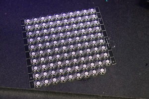
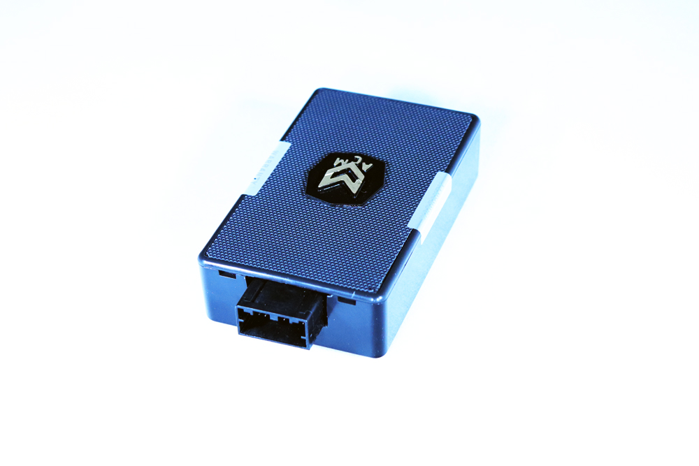
Our MCU package needs to incorporate all the components necessary for the project. We designed custom boards and had them manufactured. The unit includes our Teensy MCU along with 3 CAN bus transceivers, one BLE board, various logic level shifters to handle the LED data connections, and various voltage regulators/transformers.
It’s all packaged nicely in a custom case.
Conclusion – How Well Does it Work?
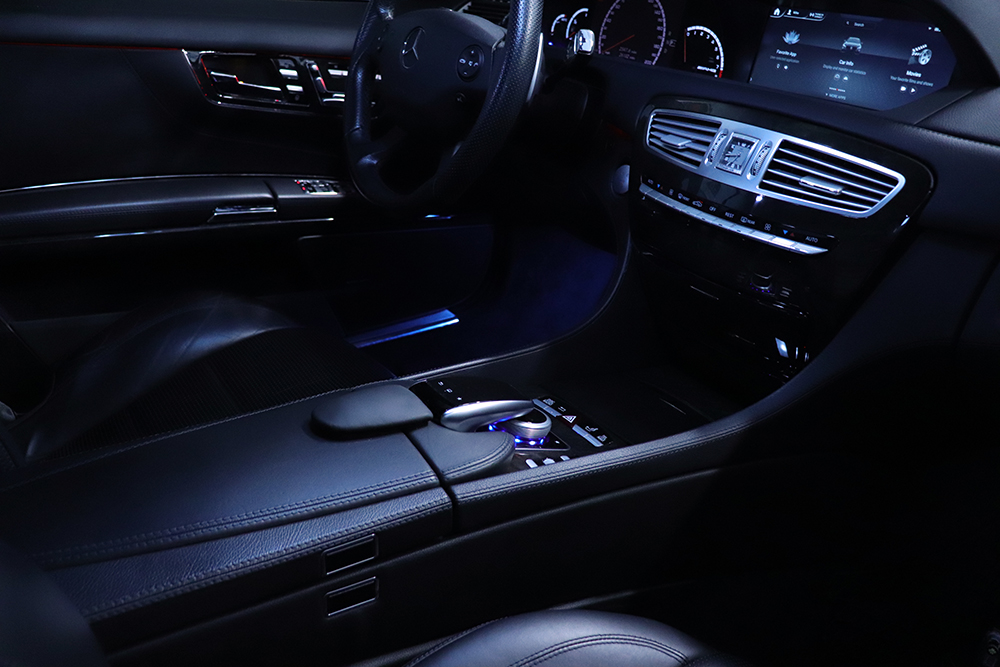
Does it all work? Absolutely. The ability to switch between HUD/Android/COMAND controls seamlessly is priceless in a vehicle. Touch screens are great if you’re stationary. If the vehicle is moving you, as the driver, simply do not have the time to focus your attention for seconds at a time on finding the correct button on a screen filled with buttons and controls.
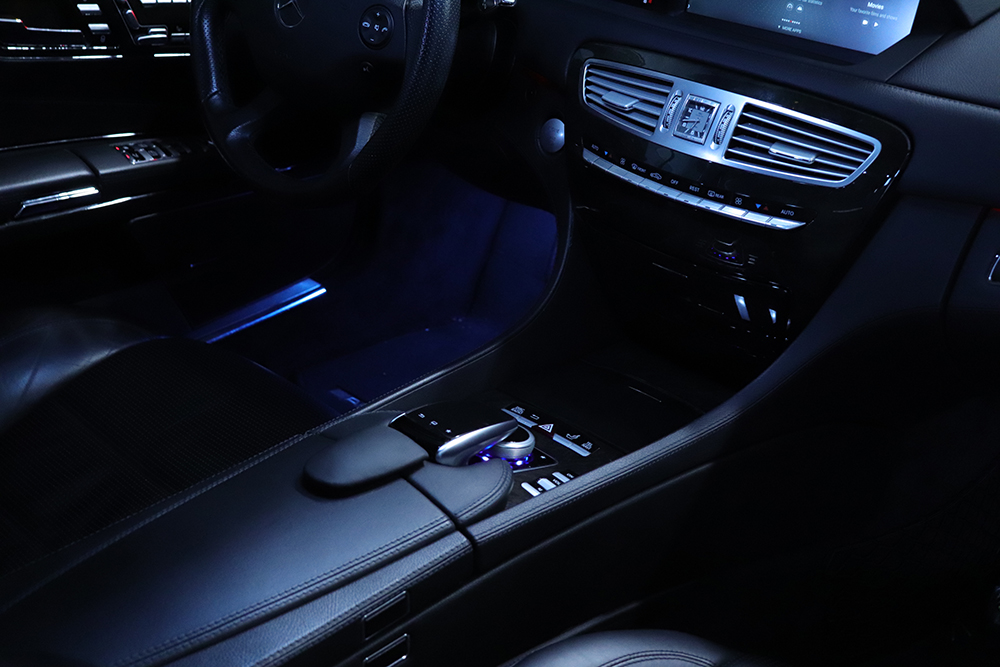
Overall, the process was fairly complex. It involved:
-extensive 3D printing of new brackets and mounting solutions with specialized tough resins.
-disassembling existing hardware and rewiring components.
-reworking/cutting the center console to make room for new components.
-cutting the existing wood trim to fit the new W222 controller.
-modifying and reupholstering the OEM palm rest to fit the new W222 controller.
-sourcing the specialized Mercedes connectors to keep wiring as OEM as possible.
-having custom circuit boards manufactured that integrate all necessary electronic components for the project.
-reverse engineering CAN bus communication between W216 controller and W216 vehicle.
-reverse engineering CAN bus communication between W222 controller and W222 vehicle.
-reverse engineering BLE communication between Navdy HUD and its dial/controller.
-extensive coding of firmware to allow passthrough communication between W216 vehicle and W216 COMAND controller while injecting modified payloads, in real time.
-coding to allow for BLE communication between MCU and Navdy HUD
If you are interested in integrating this controller into your W216 or W221 vehicle, contact us: info@absolutecarmods.com.


